
Before you start
This guide covers installation of the Tintic cone valve assembly only. Refer to your OEM service manual for fork disassembly, cartridge disassembly, cartridge reassembly, fork reassembly, oil specifications, and torque values not listed here.
This product should be installed by an experienced suspension technician. If you aren't comfortable servicing cartridge forks, find a shop in the Tintic Preferred Tech Network.
You already know how a cartridge fork works. This guide only covers the installation of the Tintic cone valve.
Read this guide end to end before you start. If anything looks different from what's described here, stop and contact Tintic.
Pre-flight check
Inspect the rod and cartridge for damage.
A new cone valve will not fix a failing cartridge seal. Resolve this first.
Record your clicker settings
Count and write down both settings before disassembly: compression clicks out from full stiff, and rebound clicks out from full stiff.
Kit contents
Verify your kit contains the following before beginning. If anything is missing, contact Tintic before proceeding.
| Part | Qty / leg | Notes |
|---|---|---|
| TAP | 1 | Replaces the stock TAP. |
| Stem | 1 | Bolt that clamps the stack onto the TAP. |
| Tintic piston | 1 | Proprietary to the cone valve system. |
| Cone | 1 | Tintic geometry. |
| Coil spring | 1 | 25Nm standard. Other options available. |
| Piston friction band | 1 | Installed on the piston. |
Parts pictured are from the WP CC Xplor/Xact kit. Every kit carries the same parts, machined to fit its platform, so yours may look slightly different.
Required tools
| Tool | Purpose |
|---|---|
| 17mm wrench | Counter-hold on TAP hex |
| 10mm wrench | Unscrewing the OEM nut |
| Torque wrench (Nm range) | 10mm socket |
| Flat bastard file | Peen removal, thread cleanup |
| MAP gas torch | Breaking Loctite on old TAP |
| Soft jaw 12mm, 12.5mm or 14mm clamps | Holding the rebound rod |
| Red Loctite (262 or 271) | TAP and stem threads |
| 6 ID, 8 OD spacer shims | Increasing float |
| 12 ID, 16 OD spacer shims | Decreasing float |
| Seal grease | For rebound needle |
| Contact cleaner | Cleaning shims and threads |
| Feeler gauges | Verifying float |
| Clean rags | Cleaning |
| Calipers | Measuring shims |
| Compressed air | Blowing out cross-holes and drying parts |
A heat gun won't get hot enough to break the factory Loctite on the TAP. MAP gas or propane is required.
Entry
Refer to your OEM service manual to remove the fork from the bike, disassemble the fork, disassemble the cartridge, and extract the rebound rod. Return to this guide with the rebound rod on the bench, stock mid valve assembly accessible.
Stock mid valve removal
Work clean. Contamination in the cartridge will cost you later.
- 01
Wrap the polished section of the rebound rod with a clean lint-free cloth.
- 02
Secure the rebound rod in the vise using shaft round soft jaws (12mm slot).
WarningAny damage on the rebound rod surface will destroy seals and leak damping pressure. Treat this rod like the precision part it is.
- 03
File the peen off the top of the TAP post with a file. File down to the root of the thread so the stem can unscrew cleanly. Unscrew the nut and set it aside (you won't need this for the following steps as it's replaced by the Tintic stem). The rebound shim stack and the stock piston can now be removed.
The factory peens the top of the post threads to lock the stem in place. Filing restores the threads. You don't need to take off much metal, just the deformed portion.
- 04
Lay the rebound shim stack out in the exact order of removal on a clean white surface. Photograph or document the stack.
WarningRebound shim stack order is critical. Lose the sequence, lose the rebound tune. The rebound stack is the only part reused from stock.
- 05
Set aside the stock piston (you won't need it during the following steps). Remove the stock mid valve shim stack and any packing from the TAP shaft and discard.
The Tintic cone valve replaces this entire assembly. Only the rebound shim stack is being reused.
- 06
If there is oil on the original TAP, wipe it off with a clean rag. Put the rod back in the vise with soft jaws. Apply heat to the TAP with the MAP gas torch. Heat evenly for 10 to 15 seconds to break the factory Loctite between the TAP and the rebound rod. Aim the torch away from the spring and toward the TAP. The goal is getting the Loctite past its release temperature. The part doesn't need to glow.
- 07
Unscrew the old TAP from the rebound rod and set aside (you will not need it during the following steps). Set aside the rebound needle and top-out spring to use later.
- 08
Clean the rebound rod and threads with contact cleaner. Blow dry with compressed air. Inspect the rod threads for burrs or damage from the heat and removal. Ensure threads are clear and brush away old Loctite as needed. This is applicable to KYB and Showa, as WP threads are internal.
- 09
Inspect the rebound rod for pits, scoring, or bends. Sight down its length against a light source.
WarningDeep scoring or a bent rebound rod will leak damping pressure and cause binding. A new cone valve won't fix a damaged rod. Address it before proceeding.
Cone valve assembly
The old mid valve hardware is gone. Build the Tintic assembly on the rebound rod, bottom up. Take your time on the stack.
- 10
Put the top-out spring back on the rebound rod and drop the rebound needle into the rebound rod. Does not apply to Showa since it's a captured needle.
- 11
Apply one drop of red Loctite (262 or 271) to the rebound rod threads. Thread the new TAP onto the rod by hand until it bottoms. Snug with a 17mm wrench. The Loctite is the anti-back-off measure. Don't over-torque.
- 12
Slide the coil spring onto the TAP shaft.
- 13
Slide the cone onto the TAP shaft. The pointed end (nose) faces up, toward the piston.
WarningIf the cone is installed backwards, the fork will have zero meaningful mid valve damping. Confirm orientation before proceeding.
- 14
Ensure the piston friction band is on the Tintic piston and seated cleanly in its groove.
- 15
Install the rebound shim stack onto the piston in the exact order it was removed. Reference your disassembly photograph/documentation.
- 16
Install the Tintic piston onto the TAP. The recess faces down. That is the cone mating surface. The piston face shoulders against the nose of the TAP.
WarningReversed or missing rebound shims will fundamentally change rebound damping. If you lost the order, contact Tintic for the stock stack reference.
- 17
Spray the entire stack assembly with contact cleaner. Blow dry with compressed air.
This removes any debris trapped between shims during handling.
- 18
Hand tighten the stem down through the rebound shim stack and piston, into the TAP.
- 19
Verify float with feeler gauges. Place feeler gauges between the spring and the base of the TAP. The measured gap should be approximately 1mm. If one side of the spring measures differently than the other side, measure both sides and set the float to an average of 1mm between the two sides.
WarningDon't guess float. Measure it.
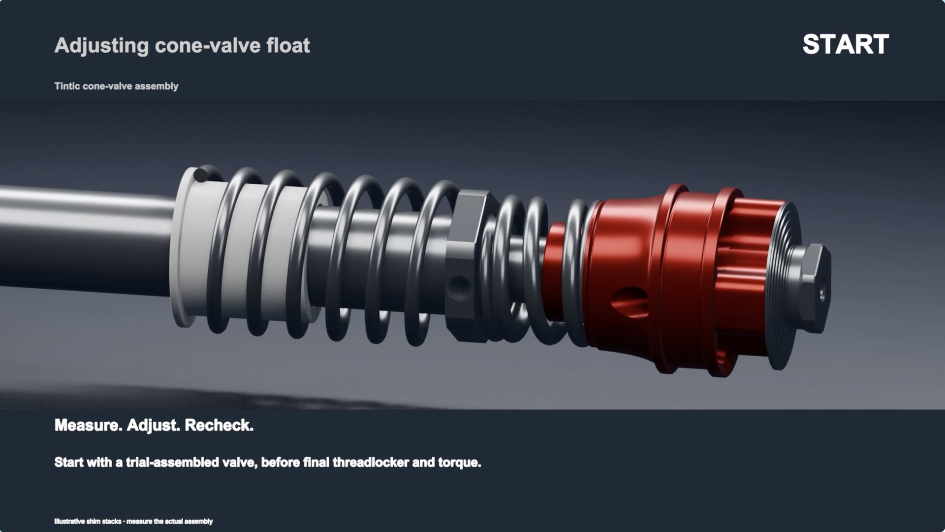
Video: Adjusting cone valve float, 1:00 · tintic.works/install-guide#step-19 Increase the float by adding 6 ID, 8 OD spacer shims between the TAP and the recessed end of the piston.
Decrease the float by adding 12 ID, 16 OD spacer shims between the cone and spring.
- 20
With the spacer shims set, remove the stem and the 6 ID, 8 OD spacer shims from the piston and TAP. Apply one drop of red Loctite (262 or 271) to the stem threads, reinstall the 6 ID, 8 OD spacer shims, and rethread the Loctited stem down through the rebound shim stack and piston, into the TAP. Any 12 ID, 16 OD spacer shims stay in place under the spring. Clamp back in the vise and torque to 6 Nm with a torque wrench while holding a 17mm wrench on the TAP body hex. Refer to the reference at the end of this guide for suggested settings.
WarningOver-torquing the stem will crush shims and destroy the stack tune. 6 Nm. Use the torque wrench.
- 21
Verify there is no axial play in the assembly. The piston and shim stack should be firmly clamped against the TAP nose with zero slop.
Exit
Refer to your OEM service manual to reinsert the rebound rod into the inner cartridge, bleed the cartridge, reassemble the cartridge, reassemble the fork, set oil volumes and levels, and reinstall the fork on the bike.
Repeat the entire procedure for the second fork leg where applicable.
Float setting
| Discipline | Float | Character |
|---|---|---|
| Hard Enduro | 1.0 mm | Maximum plushness on rocks and ledges |
| Singletrack | 0.95 – 1.0 mm | Compliant on roots and chatter, still composed |
| Desert / Endurance | 0.5 – 1.0 mm | Balanced for high-speed and slow tech |
| Motocross | 0.3 – 0.75 mm | Firmer chassis, holds up in G-outs and braking |
Current kit ships at approximately 1.0mm float by spring tolerance. This is the right default for the majority of riders across desert, enduro, trail, and extreme enduro.
Tuning notes
The cone valve intentionally reduces tuning complexity. In most cases, the cone with 25Nm spring and ~1mm float is the correct setup. If you need to change something, adjust float first. It has the most impact.
Base valve tuning is independent of the cone valve and can be handled per your OEM service manual as part of a complete fork service. Many tuners take this opportunity to tune the base valve for a fully balanced setup. That adds time but delivers a more complete result.
First ride
The cone valve doesn't need a mechanical break-in. The first thirty minutes of riding is when you calibrate your feel for the new damping character. Ride familiar terrain first. The cone feels different from a shim stack: smoother through sharp hits, more progressive through the stroke. That's by design. Give yourself time to trust it.
Troubleshooting
| Symptom | Likely cause | Fix |
|---|---|---|
| Fork feels harsh on small chatter | Float too low, or inadvertent preload on cone spring | Verify float with feeler gauges. Confirm spring is not preloaded against the cone. |
| Fork dives excessively under braking | Base valve too soft, or float too high for discipline | Reduce float. If persistent, tune base valve compression. |
| No rebound damping, fork pogo-sticks | Rebound shim stack installed backwards, delta shims, missing shims, or stem not fully torqued | Disassemble and verify rebound stack order against your disassembly photograph. Re-torque stem to 6 Nm. |
Technical support
If something doesn't look right, doesn't feel right, or doesn't match this guide, stop and reach out. We'd rather answer a question than troubleshoot a problem.
This document is the property of Tintic Works. Intended for use by experienced suspension technicians only. Tintic Works is not responsible for damage resulting from improper installation, use of incorrect tools, or deviation from these instructions. Always refer to your OEM service manual for fork-specific specifications including oil weights, volumes, and torque values not listed here. Contents may be updated without notice. Verify you have the latest version at tintic.works.